
本日は、パケットトレーサーでスタティックルーティングの設定を行います。
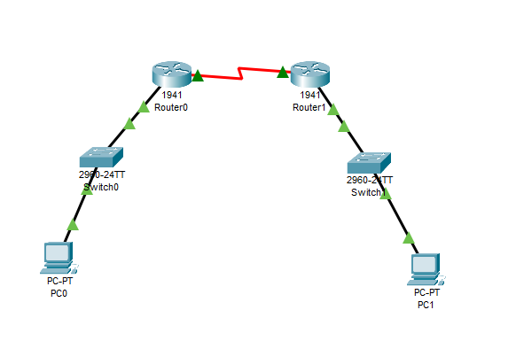
想定するネットワーク構成は下記の図のようになります。
拠点Aと拠点Bのネットワークがあります。
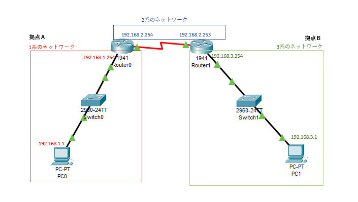
拠点Aは、「192.168.1.0」のネットワークです。
拠点Bは、「192.168.3.0」のネットワークです。
拠点Aと拠点Bをルータで接続します。ルータ間は192.168.2.0のネットワークになります。
パケットトレーサでの設定の流れとしては、トポロジーを作成し、各機器にIPアドレスを作成した後にルーティングを設定します。
トポロージーの作成
トポロージーを作成します。
・ルータ 2台
・スイッチ 2台
・パソコン 2台
ルータから作成します。
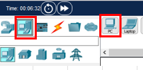
左下の「Network Device」をクリックし、次に「1941」のルータをクリックし、ルータをドラッグして配置します。
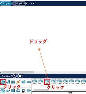
ルータが配置されます。
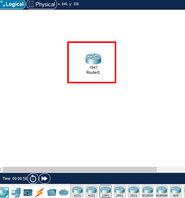
同じように各機器を配置していきます。
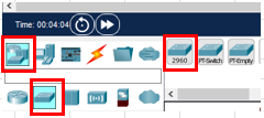
スイッチは、「Network device」から「Switch」を選び、ここでは「2960」を選びました。
2台配置します。
続いてパソコンを配置します。
「End Device」から「PC」を選択し、配置します。
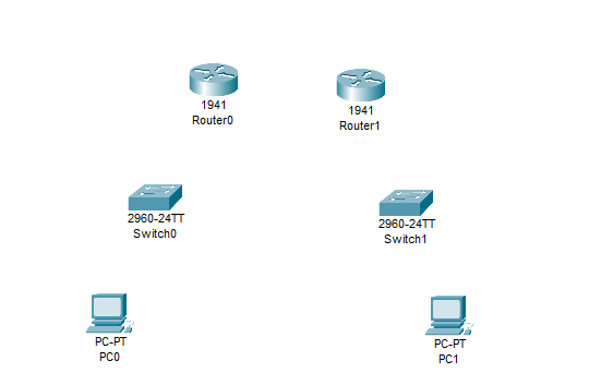
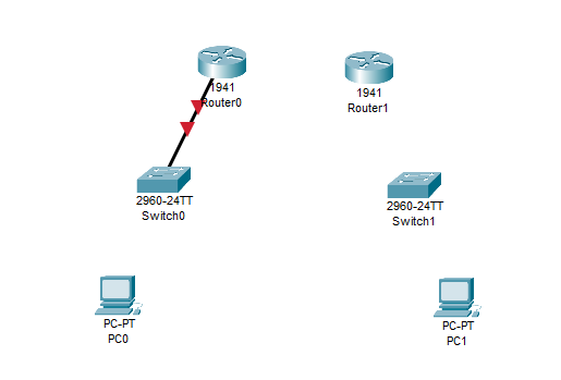
各機器を配置すると下記のようになります。
続いて、各機器をケーブルで接続します。
ルータとスイッチは、ストレートケーブルで接続します。
・ルータ側 ストレートケーブルを指すポートは、GigabitEhernat0/1とします。
・スイッチ側 ストレートケーブルを指すポートは、fastEhernat0/1とします。
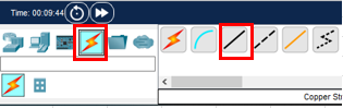
最初にケーブルを選択します。
「Connections」から「Copper Straight -Through」をクリックします。
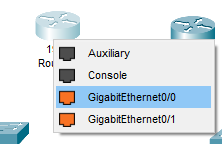
ルータ0をクリックし、「GigabitEthernet 0/0」をクリックします。
スイッチ0を選択し、「FastEthernet 0/1」を選びます。
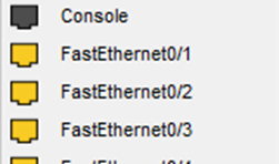
ルータ0とスイッチ0が接続されました。
続いて、スイッチとPCをストレートケーブルでつなぎます。
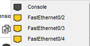
スイッチを選択し、どのポートでも構いませんが、ここでは「FastEthernet0/2」をクリックし、
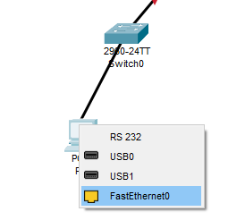
PCと接続します。PC側は
PC側は「FastEthernet0/2」を選びます。
下記のようになります。
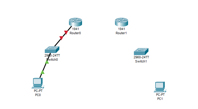
同様に「192.168.3.0」のネットワークもそれぞれストレートケーブルで接続していきます。
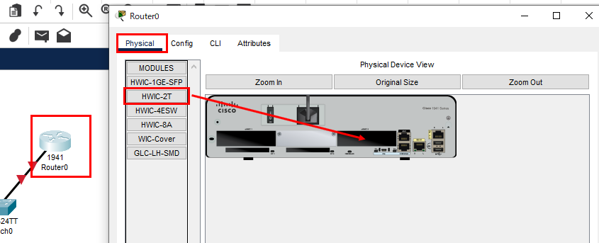
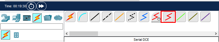
続いて、「Router0」と「Router1」を下記赤枠の「シリアルDCE」で接続したいのですが、
まずは、ルータの設定を行う必要があります。
「Router0」をクリックすると下記ウィンドウが表示されます。
Physicalタブをクリックし、HWIC-2Tを選び、矢印のようにドラッグします。
HWIC-2Tは、ルーターやスイッチに追加のシリアルポートを提供するための拡張カードです
拡張したら電源をONにします。(クリックします。)
ONすると赤枠部分が、緑色になります。
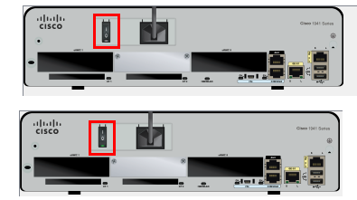
「Router1」にも同様にHWICを追加し、電源をONします。
続いて、router0とrouter1を「シリアルDCE」で接続します。
シリアルDCEは下記赤枠のケーブルです。
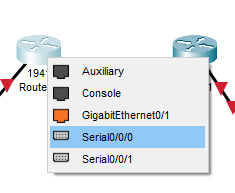
「router0」をクリックし、Serial0/0/0をクリックします。
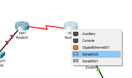
「router1」をクリックし、こちらも Serial0/0/0をクリックし接続します。
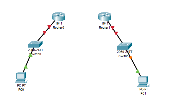
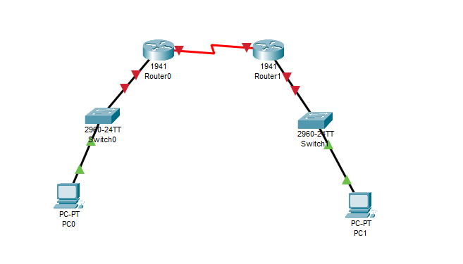
これでトポロジーが完成しました。
IPアドレスの設定
続いて、機器のIPアドレスを設定していきます。設定するのはPCとルータです。
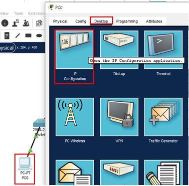
PC0をクリックして、表示されたウィンドウで「Desktop」タブをクリック、「IP Configuration」をクリックします。
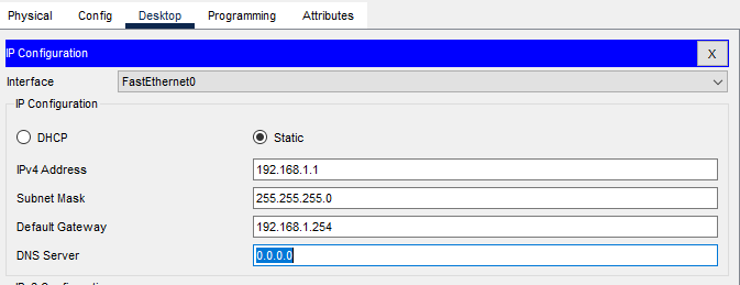
下記のようにIPアドレスを設定します。
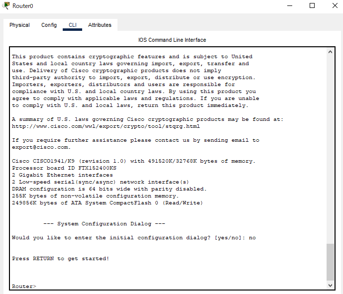
続いてルータのIPアドレスを設定します。
ルータをクリックし、電源がONになっていることを確認し、「CLI」タブをクリックします。
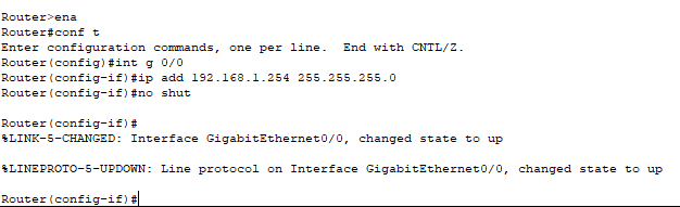
続いて、下記のコマンドを打ち、IPアドレスを設定していきます。最初にLAN側のIPを設定します。
>ena
>conf t
>ing ena
>conf t
>int g 0/0
>ip add 192.168.1.254 255.255.255.0
>no shutdown
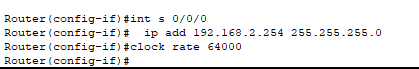
続いてWANのipアドレスを設定します。
>int s 0/0/0
>ip add 192.168.2.254 255.255.255.0
>clock rate 64000
exitし、下記のコマンドでスタティック(静的)ルートをいれます。
>exit
>ip route 192.168.3.0 255.255.255.0 192.168.2.253

スタティックルートについて補足説明します。
ルーティングテーブルの追加に関しては、足りないルートを入れていきます。
拠点Aのルータから見ると
192.168.1.0は直接つながっているのでわかる
192.168.2.0も直接つながっているのでわかる
192.168.3.0は、わからないので、192.168.3.0を追加する
192.168.3.0がどこにあるか→次のルータの場合は、そのIPアドレスを指定する。
192.168.2.253に飛ばせば、192.168.3.0があるので、コマンドの指定は下記となります。
ip route 192.168.3.0 255.255.255.0 192.168.2.253
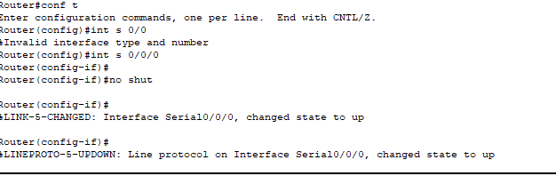
設定を反映するため、no shutdown コマンドを実行します。
>int s 0/0/0
>no shut
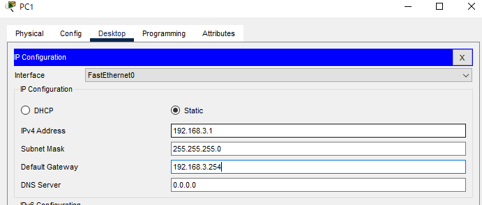
続いて、192.168.3.0のネットワーク側のPCとルータのIPアドレス設定を行います。
PC1のIP configuration です。
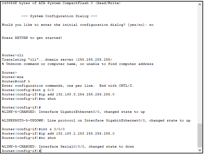
続いて、Router1の設定です。
ルータBの設定
>cli
>ena
>conf t
>int g 0/0
>ip add 192.168.3.254 255.255.255.0
>no shut
>int s 0/0/0
>ip add 192.168.2.253 255.255.255.0
>no shut
>exit
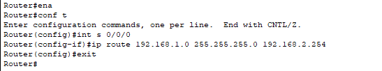
Router1のスタティックルートを設定します。
>ena
>conf t
>int s 0/0/0
>ip route 192.168.1.0 255.255.255.0 192.168.2.254
>exit
トポロジーを見ると下記のようになっています。
ルーティングの確認
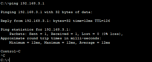
では、実際にPC0(192.168.1.1)からPC1(192.168.3.1)が通信できているかPingコマンドで確認します。
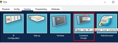
PC0をクリックし、DesktopからCommand Promptをクリックします。
Pingを実行します。
>ping 192.168.3.1
pingの応答があります。
まとめ
本日はスタティックルートの設定についてでした。